|
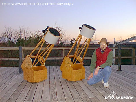
Two
10" Dobsonians I have built: I
have built several dobsonians of this type (three 10" and
one 18") these are like the 18" in that they are made
of 3/4" oak plywood and have solid oak trusses. They were
a good learning experience that prepared me for the problems
I would run into building the 18". |
 |
The
18" Before Finish was applied:
I usually use the instrument for several months before applying
the finish so that I can make any modifications that may become
apparent with use. Once I have a tried and true design, then
I apply the finish coat. |
 |
The Finished
18": Applying the finish
to all the parts takes almost as long as building the scope.
It has two coats of stain and four coats of polyurethane applied
with an airless sprayer. |
 |
The 18"
With Shroud: My wife made
a black shroud out of a black slightly elastic cloth. |
 |
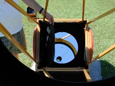
The
18" and its Mirror Cover (Before Finish): The hinged mirror cover shows better before
it was painted black. The hinges are standard spring loaded cabinet
type. |
 |
The Finished
18" Mirror Box: Now
the flat black paint has been applied. I use Krylon Ultra Flat
Black. Its odd stuff and if it is too hot when spraying it doesn't
stick, but simply forms a black powder on the wood! Putting the
can in the frige for thirty minutes does the trick. |
 |
The 18"
Wood Finder: Years ago I
purchased a pair of Celestron 11x80 binoculars that were badly
out of alignment. Since they were useless as binoculars I salvaged
the optics and built the finder you now see with wood to match
the main scope. There is a front surface flat inside the box
which allows the light to enter a conventional 1 1/4" eyepiece
rather than a small 1" eyepiece. |
 |
The
Secondary/ Spider Cage:
This assembly is simply made from plastic laminate wrapped and
glued around two wood rings. There is no other structure inside,
the laminate is its own structure. It is very light yet strong. |
 |
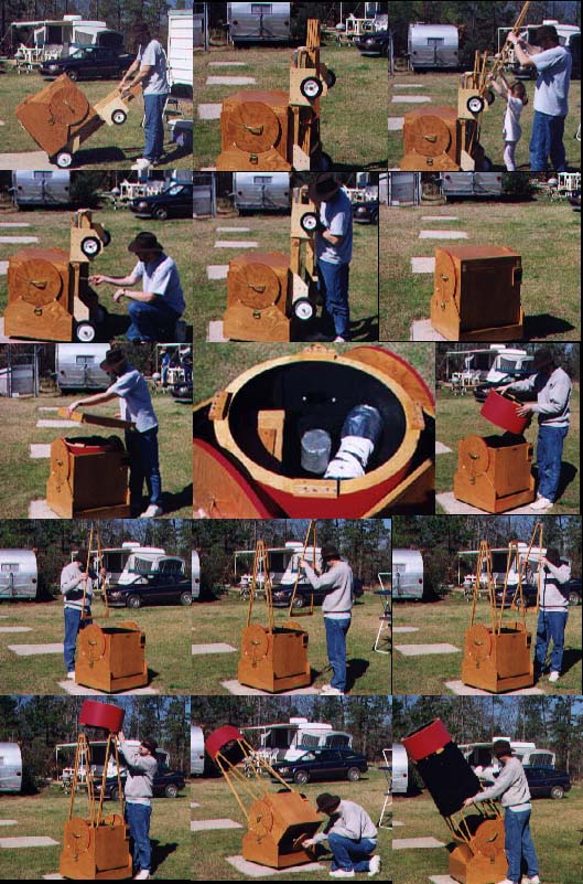
A sequence
showing the assembly of 18":
As can be seen the upper cage stores inside the mirror box and
a custom hand cart attaches to the rocker box and mirror box
for easy transport. |
 |
The rear
of the Mirror Box and Fan:
The three knobs are for primary collimation. The knobs are from
Reed Tool Supply (no relation). The mirror cell floats on three
valve springs (from a car engine) which are the only springs
I could find strong enough to support the 50 pound mirror. The
cell is a 9 point flotation type with the three triangles made
of 1/2" aluminum. The three eye bolts are for locking the
cell once collimation is achieved. There is a hole in the center
of the cell which houses a muffin fan for cooling the mirror. |
 |
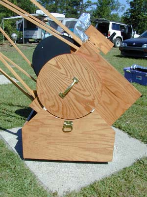
The
Teflon Bearings: I use 1/4"
thick Teflon sheets which I cut into squares using a radial arm
saw. Holes are then counter sunk so that screw heads will not
protrude and scratch the laminate bearings. The side bearings
are disks of plywood cut in a circle and edged with plastic laminate
(Formica). In this way I can have a bearing of any diameter. |
 |
The
18" Mirror: comes from
Pegasus Optics formally of Huntsville, AR. The mirror is high
quality and even gives good planetary images. |